Modular Rail Modelling in New Zealand

Friday, February 26, 2010

Goods shed!

Another quick update before a full post this weekend. This week I built the first of the new structures: a goods shed. It still needs a bit of detailing and work on the surrounds, but it does the job. It's made out of styrene and a bit of mdf for the steps. It's airbrushed with my crappy Tamiya Sprayworks, and weathered with a bit of dry brushing and an oil wash.

Photobucket

Photobucket

Sunday, February 21, 2010

Laying the track, part 2

In the last of the build posts I got to the stage where the roadbed was down, and the modules awaited their track. One thing I did to at this stage was to drill the holes in the module ends through which the connecting bolts would go. Once this was done, I bolted the modules together. Most of the joins were nicely flush, but there was a bit of sanding needed here and there.

Photobucket

I decided to lay the track on the bridge module first to get a bit of practice before moving onto the more complex track arrangement on the yard sections.

Photobucket

Stage one of laying the track was attaching the track to the outer edge. Because it is inevitable that the sharp track ends will be accidentally snagged at some stage, it is necessary to fix them at the edges. I decided to drive nails in alongside the track, and then solder the rails to these. While this works satisfactorily, it doesn't give the cleanest look. In the future I will solder the rails to screws driven in directly under the rails.

Photobucket

The track on the river section amounted to one and a bit lengths of flex track, so the appropriate length of flex track was cut with the Dremel cutting tool. After soldering the track sections together at the joiner, I soldered feeder wires to the bottom of the track, and fed these through holes I had drilled in the basedboard. I then glued the track down with PVA, and soldered the other end to the nails. A few dabs of PVA is strong enough for gluing the track down at this stage, because once the track is ballasted, there is no way it's coming back up again! Finally, I filed down the track ends flush with the end of the modules.

Next, I moved onto the yard sections, again starting at the edge and moving inwards. As predicted, the yard section was much more complicated. For a start, fitting the points together in the desired arrangement meant trimming the sleepers in various places. Thinking ahead, I drilled holes beneath the points in the appropriate places so that point motors could be attached at a later date. Also, I removed a couple of sleepers form each end of the points to make attaching and soldering the rail joiners an easier job. Replacing these sleepers would be one of the last jobs of the track laying.

Photobucket

Attaching the various feeder wires also took time. To simplify matters, I added feeders to all of the sections of track so as to not rely on the contact of the point blades to feed the sections of track with electricity. I had always planned on running the modules with DCC, and thankfully this makes wiring a great deal more simple. Still, I expect I could have got away with fewer feeders, but I thought the extra time spent adding them would ultimately mean better running performance in the future. With this in mind I also decided to solder all the rail joiners, though this was a decision I was not entirely happy with later on, as I will explain in a future post.


Photobucket

After a great deal of cutting, trimming, soldering, hole-drilling, and filing (and some annoyed swearing), I finished laying the track. At this stage I had not glued it down, as I thought it was wise to thoroughly test the track for a period before fixing it permanently.

Photobucket

I was pretty satisfied with how things had gone, and glad to be finished. I'm in awe of those modelers who hand build track; for me laying commercial track is enough of an ordeal. Still, time and effort put in at this stage of the build is crucial to the running quality you eventually get.

Photobucket

Next time: starting on the scenery.

Saturday, February 20, 2010

Power poles!

Just a quick update of today's work. I bought a number of Woodland Scenic trees, and a whole bunch of styrene. Out of the latter I made some power poles, painted and weathered them and put them on the layout. I also got some corrugated sheeting and clap board to build two new buildings, which I'll start on tomorrow. I'm really pleased with the power poles; it seems to be the little details that lift the layout.

Photobucket

Photobucket

Sunday, February 14, 2010

Laying the track, part 1

Having finished the benchwork, it was time to think about what to put on them. I had made some rather elaborate plans for the modules based on Otira, but I had long decided to drastically simplify these so as not to bite off more than I could chew. Building these modules already involved a number of techniques that I would be trying for the first time, and there was quite a lot to do, so I would keep things simple.


As noted, I had decided to use Peco Code 80 track, and already had a number of large insulfrog points.

Photobucket

I went back into Acorn Models where they had a box of Peco Code 80 flextrack, so I bought twelve pieces which would turn out to be be sufficient for all three sections. I set these out on the modules, and then tried various track arrangements. I also used my half-completed Dx as a prop to get a sense of the scale. It soon became obvious that the 450mm by 1200mm size of the sections offered plenty of scope in this scale. After a lot of thought I settled on the present arrangement.

Photobucket

Photobucket

The next challenge was the road bed. In the past I had used 5mm cork tiles, which were cut to fit with a craft knife and then glued down with PVA. On the join between modules I thought it necessary to have a firm surface under the track to avoid damage to the track at the edges, so intended to have a section of the roadbed made from mdf on either module edge.

A sudden brainwave led to the decision to have the whole roadbed cut from the 5mm mdf that was left over from the construction of the benchwork. This would be a whole lot simpler than the cork method. The disadvantages of this method were the potential sound problems which cork can help with, and also that unlike soft cork, it would not be easy to pin the track to the mdf surface. Given that I usually glue the track down, I decided that this last disadvantage was not a major problem, so I went with the mdf plan.

Getting out my cheap (and worryingly erratic) jigsaw, I cut the roadbed pieces to shape, including a section that would end up being the bridge. Then, using the sanding drum on my Dremel, I shaped the edges of the roadbed. I bought the Dremel to aid with cutting track, which it does awesomely; but it has ended up being hugely useful for all sorts of purposes. Best tool ever!

Photobucket

The roadbed sections were glued and screwed down, and then painted with a ground colour. This was sort of pointless, because the roadbed and track would eventually be airbrushed a dark brown anyway. I'm sort of picky and like to have things looking neat as I'm building them, even if it occasionally means putting in work that won't be scene in the finished product.

Photobucket

With this finished, it was time to start thinking about laying the track. This is where things stood for about a week. Everybody has bits of the hobby that they do not entirely enjoy, and for me this has usually been laying track, though I'm not sure why. Maybe it's because you have to be very methodical to get the track just right. Anyway, while I worked up my enthusiasm for laying the track I also had a chance to plan the wiring.

Photobucket

Next post: laying the track.

Monday, February 8, 2010

Construction begins

I had used dressed timber and mdf on my previous layout with no hitches, and so having worked out the amount of material I would need for three 1200mm by 450mm modules, I headed down to the local Placemakers with a friend and his overly large trailer. I got around 5 metres each of 90mm planks, and 30mm by 40mm timber for the legs. I also picked up several sheets of 6mm mdf, screws, glue, and chicken wire. All this was eye-wincingly expensive, but it's nice to work with the right materials.

Photobucket

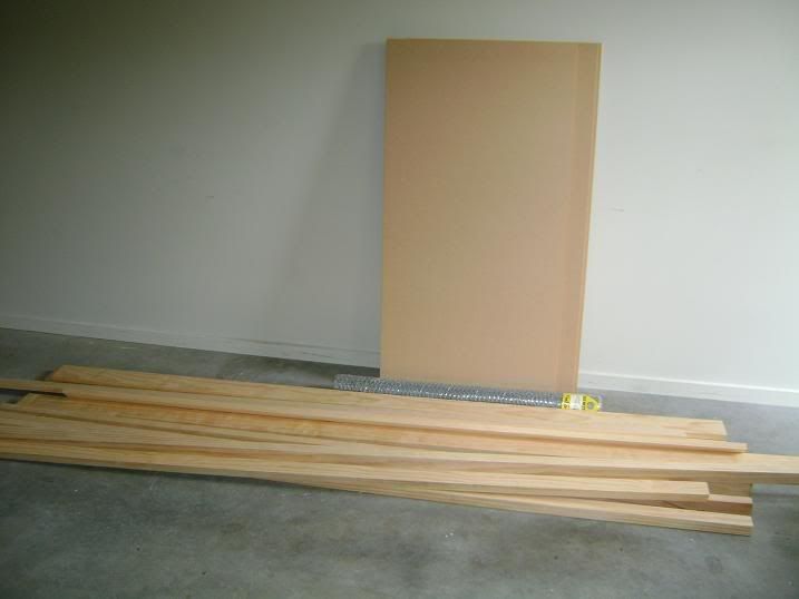
Back home, I sat and stared at the pile of wood for a couple of days. My woodworking skills are not the best, so I was a bit hesitant about starting. I also wanted to think through the construction sufficiently so to avoid mistakes along the way. You'll also note that I'm fortunate enough to have a clean, well-lit, and warm garage to build in, although it does get cold in winter.

I wasn't overly concerned with the weight of the modules, as I reckoned these will spend most of their time set up in the garage. I settled on a framing the modules with the 90mm timber, with a couple of cross braces. These were all screwed and glued together with minimal fuss, and to my surprise were mostly square!

Photobucket

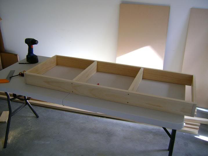
The mdf sheets I used are 1200mm long, so only the edge of a mdf sheet needed to be cut to get the correct size, and this was fixed to the top of the frame after pre-drilling all of the screw holes.

I finished off the three modules over the course of several evenings, and over all the process was a lot of fun. I'd like to get some power tools in the future for this kind of thing, because I used a handsaw throughout. A saw bench would be awesome!

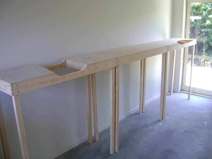
The next challenge was attaching the legs, and I decided to use bolts and wingnuts, so it was back to the local Placemakers for these. The module standard designates a railhead height of 1200mm, which I think is ideal, though some people might find it a smidgen high. Before attaching the legs, I had wondered how stable the whole arrangement would be at this height, but after the legs were on it proved to be very stable. I looked around on the internet, and others have used a similar solution. Lots of hole drilling later, the modules were ready to assemble.

Photobucket

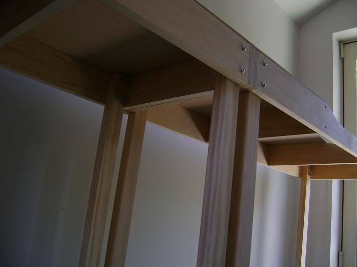
At this stage, the legs still need their adjustable feet, and I've purchased a couple of hundred (!) T-nuts for this purpose.

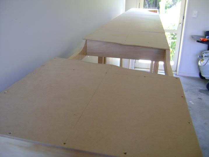
Here you can see how the legs are attached each with two bolts:

Photobucket

You will also note that two of the modules have cut out sections for the scenery. Lots of layouts I see have no depth beneath the railhead, with the track just plonked down on a flat piece of plywood. This often strikes me as really artificial, and would look especially so for the undulating countryside on New Zealand that I intended to model. So a little planning ahead was needed at this stage to envisage where the track was going to go, and how it would be situated in the landscape. One cut out was for a river I intended to build. Everyone loves a river!

Photobucket

Next post: planning the track layout and laying the roadbed.

Saturday, February 6, 2010

Back to the the beginning...

My intermittent interest in model railways was rekindled last year by a visit to the yearly Christchurch train exhibition, where there were a couple of 3/16ths scale New Zealand prototype modular layouts, and also a trip I made on the TranzAlpine to escape Christchurch for the weekend. Riding the train back from Greymouth, my imagination was again captured by the great scenery, and the potential to model this unique landscape.

My previous layout, which I built in 2007, was a roundy-roundy arrangement with a scenic area on the front and a staging yard at the back. It was based somewhat roughly on the West Coast side of the Midland Line. It was fairly successful, and I learnt a great deal while building it, but ultimately I felt it was flawed and lacked further potential. I was also having difficulty at the time working out where I was going to get rolling stock from, and my enthusiasm for the hobby diminished rather quickly after a huge pile of work landed on my desk. The layout was eventually sold on Trademe, but I figured that it had served its purpose as a bit of fun and a learning experience.

Photobucket

I had considered building another circuit layout, but I was ultimately unsatisfied with the realism and scope a manageable layout could offer, so these plans came to nothing. After seeing the modular layouts at the Christchurch show, however, I became convinced that a modular layout was the way to go. Here was something I could make a start on, and its modularity meant that the layout could develop and grow over time as my enthusiasm dictated.

I had been lurking at NZ120.ORG, and so I posted a thread about the possibility of forming a modular group, which quickly led to a long discussion about modular standards (that I will not repeat here). After a lot of discussion, a rough Free-mo standard was developed. It can be found here.

I was ready to start building. After a lot of thought and revised plans, I decided to build a freelance module based on a South Island location. I think that Free-mo is suited to freelance subjects, because ultimately the modules will be joined up in ad hoc and unrealistic arrangements anyway, and what is needed in a Free-mo module is something that is going to make a functional contribution to a layout. I haven't ruled out building something more prototypical in the future however. Thus the idea with this module was to build a yard that would be functional in a Free-mo layout, allowing for the staging of trains. The design would have a couple of passing loops, sidings, and a head shunt. I jotted down my rough plans on a piece of paper, and then calculated a list of materials.

Actually, this is a gross simplification of how it all came about, but I'll spare you the interminable sequence of decisions I made and latter revised!

Next post: buying supplies and making a start on the modules.